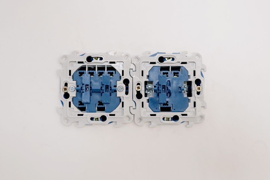
Installing a Dimmer Switch: Step-by-Step Guide
Adjusting the brightness of a room’s lighting can change its atmosphere and functionality. A dimmer switch offers this flexibility by allowing the user to control the intensity of the light output. Replacing a standard toggle switch with a dimmer is a common home improvement task that can be completed with basic electrical knowledge and the right tools. This guide outlines the essential steps, safety measures, and compatibility considerations involved in the process.
Before beginning any electrical work, it is important to understand that working with household wiring involves inherent risks. The information provided here is intended for educational purposes and does not replace the judgment of a licensed electrician. HandyFix offers a range of tools and components that can support such projects, but the responsibility for safe installation rests with the individual performing the work. Local electrical codes may also apply, and consulting those is recommended before making changes to a home’s wiring system.
The following sections walk through the typical procedure for installing a dimmer switch, from turning off the power to testing the final setup. Each step is explained in a neutral, process-oriented manner to help the reader grasp the sequence and reasoning behind the actions.
Safety First: Preparing the Work Area
Electrical safety begins with isolating the circuit. The main breaker panel should be located, and the breaker supplying the switch being replaced must be switched to the off position. A voltage tester can then confirm that no electricity is flowing to the switch. This step is critical because even when the switch is off, the wires inside the box may still be live if the breaker is not turned off.
In addition to power disconnection, using insulated tools and wearing rubber-soled shoes adds a layer of protection. A non-contact voltage tester is a convenient tool to check for the presence of voltage without touching bare wires. Once the power is confirmed off, the area around the switch can be cleared of any loose materials or obstructions. Taking photographs of the existing wiring before disconnecting it can serve as a helpful reference during the installation.
Working in a well-lit space is also advisable, as dimly lit conditions can lead to mistakes. If the room itself is dark because the power is off, a battery-powered work light can provide illumination. These preparatory steps help create a controlled environment, reducing the likelihood of errors or accidents.
Understanding Dimmer Switch Types and Compatibility
Dimmers are not all identical. The type of light bulbs used in the fixture plays a major role in determining which dimmer model is suitable. Incandescent and halogen bulbs work with standard leading-edge dimmers, while many LED and CFL bulbs require trailing-edge or specifically designed LED-compatible dimmers. Using an incompatible dimmer can cause flickering, reduced dimming range, or even damage to the bulbs and the switch itself.
The wattage rating of the dimmer must also match or exceed the total wattage of the bulbs it will control. For LED bulbs, the calculation is based on the actual wattage, not the equivalent incandescent wattage. Manufacturers typically list the minimum and maximum load requirements on the dimmer packaging. Additionally, some dimmers are designed for single-pole applications, while others support three-way or multi-location setups. Identifying the wiring configuration of the existing switch is necessary before purchasing a replacement.
Another consideration is the type of wall box. Standard switch boxes are usually about two inches deep, but some older boxes may be shallower. Many modern dimmers, especially those with heat sinks or smart features, require a deeper box to fit properly. Measuring the depth of the box before buying the dimmer can save time and avoid complications during installation.
Gathering Tools and Materials
Having the correct tools on hand makes the installation process smoother. A basic set includes a flathead and Phillips screwdriver, wire strippers, a voltage tester, and a pair of needle-nose pliers. Wire nuts or push-in wire connectors are often used to join wires, and electrical tape can provide additional insulation for connections. Some dimmer switches come with their own wire connectors, but having extras is helpful.
In terms of materials, the dimmer switch itself should be chosen based on the compatibility checks described earlier. A faceplate that matches the dimmer’s design and the room’s decor may also be needed, though many dimmers include a standard wall plate. A small flashlight or headlamp is useful if the work area is poorly lit after the power is disconnected. Keeping a notepad and pen nearby allows the installer to label wires or sketch the original connection layout for reference.
HandyFix offers a selection of dimmer switches and installation kits that include some of these tools. Checking the product details for any included components can help avoid purchasing redundant items.
Removing the Old Switch
With the power off and the tools ready, the next step is to remove the existing switch. The faceplate is unscrewed and set aside. The switch itself is then unscrewed from the wall box and gently pulled outward, taking care not to tug the wires excessively. At this point, the wires are exposed and can be examined.
A typical single-pole switch has two hot wires (often black or red) connected to the screw terminals, a neutral wire (white) that may be tucked into the back of the box, and a ground wire (bare copper or green). In many older installations, the neutral wire is not connected to the switch but simply passes through the box. The ground wire is usually attached to a green screw on the switch or to the metal box. Identifying each wire and noting its condition is important before disconnection.
Using a screwdriver or pliers, the wires are loosened from the terminal screws and removed. If the switch uses push-in connections, a small slot release tool or a flathead screwdriver can be inserted to free the wires. Once all wires are detached, the old switch can be fully removed from the box. The wires should be straightened and trimmed if necessary to expose fresh copper for new connections.
Wiring the Dimmer Switch
Wiring a dimmer switch follows a similar logic to wiring a standard switch, but the number of wires may differ. Most dimmers have two black or red wires (line and load), a green or bare ground wire, and sometimes a white wire for neutral. If the dimmer requires a neutral connection, it must be connected to the neutral bundle in the box. Not all dimmers require neutral, but those with smart features or LED compatibility often do.
The installation begins by connecting the ground wire from the dimmer to the ground wire in the box. This is typically done by twisting the wires together with a wire nut or using a push-in connector. Next, the line wire from the dimmer is connected to the incoming power wire (the wire that remains live when the switch is off). The load wire from the dimmer is connected to the wire that leads to the light fixture. If the dimmer has a neutral wire, it is connected to the neutral wires in the box. All connections should be snug and covered securely with wire nuts.
After the connections are made, the wires are carefully folded back into the wall box. The dimmer is then attached to the box using the screws provided, and the faceplate is installed. It is important not to overtighten the screws, as this can crack the dimmer housing or strip the threads. Once everything is secured, the circuit breaker can be turned back on.
Testing and Final Adjustments
With power restored, the dimmer should be tested to confirm proper operation. The switch can be turned on and the slider or knob moved through its full range to see if the lights respond smoothly. If the lights flicker, buzz, or do not reach full brightness, the dimmer may be incompatible with the bulbs or the load may be outside the rated range. Some dimmers have an adjustable minimum brightness setting that can be tweaked to eliminate flickering at low levels.
Testing includes checking all connected fixtures. If multiple bulbs are on the same circuit, each bulb should react consistently. In a three-way setup, the remote switch should also be tested to ensure the dimmer works correctly from both locations. If any issues arise, the power should be turned off again and the wiring inspected for loose connections or reversed wires.
Once the dimmer performs as expected, the faceplate can be tightened, and the workspace can be restored. Regular cleaning of the dimmer’s slider or touch surface can help maintain its responsiveness. Over time, if the dimmer feels warm to the touch, this is usually normal as long as it is within the manufacturer’s specified temperature range. If excessive heat is noticed, consulting a professional electrician may be advisable.